

I have always had some interest in cryptology and secret stuff like that. I did read up on how the German Enigma worked before I ended high school so it's not precisely a new idea that I want to make a enigma replica of some kind.
Yes, it does exist several in various degree of complexity already but the interesting part isn't to have one, it's to make one so they don't count (and they all have something I don't like or missing something I want).
My plan is to make an electronic Enigma replica that on the outside looks very much like the original - as far as cost allows.
Inside it will of course be all electronic with LEDs, alphanumeric display for rotors and so on.
I have a ruff plan on how to do it in my head and as of today I have ordered a pile of parts from ebay and aliexpress so in a month or two I should be able to start assembly.
My plan is to have
* one top PCB with the alphanumeric display, the rotors (made of rotary pulse encoders and a 3D printed wheel), switches and an arduino clone.
* next PCB is just the light board with it's 26 LEDs
* next PCB is the keyboard with it's 26 Keys
* last PCB is the front side plug board with sockets and a little of smarts in it
The boards are connected with a flat cable working as a bus
By splitting up the parts design of on part can be changed without impacting the rest. The keys can be simple tactile ones with a small cap or something with a 3D printed cap that looks like original.
It also makes it easier to make it look more realistic by having the boards at different levels

I would love to have real wheels/rotors that you can take out and switch around. I have some ideas on how to make it possible but it's not that easy or cheap to implement so maybe some future version will come with that.
It's of course a ton of things to think of in order to make this project and that is just one of this things that makes it's interesting to work on it.
My current issues is how to make the PCB and learn 3D printing software. Given that I want it to be open I want to use open source tools to create it also (plus that free version of eagles max pcb size is way less than what I need) I have decided to use KiCad for my PCB but since I never used that before I need to learn it.
==================================================
Update 2015-10-15: It begun! I got the small tactile switches and mounted them on a protoboard where I'm also going to put all the LEDs once I get them.

==================================================
Update 2015-10-30: Finished soldering the keypad/lamp board and started on the rotor parts.

Top part with one wheel in place plus arduino nano (arduino uno is to big and pins not correctly spaced for this kind of protoboard)
Under is lamps for all the letters and under that is the keypad.

Lamp part and kyboard

Close up of arduino nano and the wheel part

Backside of the lamp/keyboard
==================================================
Update 2015-11-16:have now given up on the ht16k33 chip to ever arrive and got it refunded. Have now ordered another set to arrive in time for christmas.
Since I want to start playing I built it up on a breadboard with shift registers instead.


==================================================
Update 2015-11-25:
The ht16k33 arrived and I wrote some code to test it out using some other letters I got.

Top middle is the rotors
To the right is two of the letter lights
Below left is three of the keyboard keys
Bottom middle is the plugboard
Bottom right is arduino nano controlling it all
I wrote a library for the chip and posted it at https://github.com/lpaseen/ht16k33
Now it's time to get working on the first prototype, got all parts except the correct letters but by the time I soldered everything they may have arrived.
==================================================
Update 2015-12-03:
Made great progress with the code, uploaded what's written so far to https://github.com/lpaseen/myEnigma
I have code for wheels, rotors, keyboard, lamps, plugboard. What's missing is to add a switch, the enigma crypto code and tie it all together.

What this first proof of concept version will look like
Electrically it will be same as future version but the look will be way better.

Added one wheel, need to stabilize it.
Update 2015-12-11:
Mostly worked on the software but now the keyboard now got letters on the keys.
Update 2015-12-11:

Keyboard now got letters
Update 2015-12-13:
Made a simple wood frame for this prototype.

My intent is to have the physical part finished and most of the code ready before christmas. Next version will electrically be same but look a lot better on the outside.
Update 2015-12-24:
Finished up the wiring of the plugboard and added a switch plus painted the frame, it's getting close now.

Update 2015-12-26:
Did also connect plugboard so now the thing left on the physical front is
* a acrylic over the LEDs with some letter stickers to indicate letters
* letters on the plugboard
* the rotors
* the decimal point circuit
On software side all interface parts are coded, working on one last part of the encryption, then it's just to make it all usable.

==================================================
Update 2016-01-13
Have ordered the alphanumeric digits but eta is about 2 weeks (at least).
Also missing a quadnor gate for decimal point so I ordered that at the same time.
Software wise lots of improvements are now in place and bugs fixed but still missing some parts of the UI. Once the last parts are coded I will make a short video of how to handle it (and start on the user manual).
Did a test on how long 2 rechargeable AA batteries will last and after 10h it finally died. With that test I decided that it will be good enough to power it from 2xAA with external power as option.
Current goal is to have a more realistic looking one ready by fall for the makerfare then and also put it up on instructable and kickstarter.
==================================================
Update 2016-01-19
ETA for the last two components is Feb 15 so almost a month :(
Added decimal points as external LEDs so I can finish coding and that is now just about done.
I got everything to work as I want except Preset. Currently wondering about how to handle loading and saving configurations. I can do it over serial API and the first 4 can be retrieved by pressing a button under the wheel when turning it on but how to do the loading and saving with the wheels and buttons in a way that doesn't need a separate manual to be understood ?
Besides hardware and software I now need to create a userguide of some kind that explains how it works (and make a better looking one) plus of course make some PCB for all the components.
 |
| Current state - PoC almost don, just 3 things left. |
Update 2016-02-01
Have finished up maybe 90% of the schematics in KiCad.
It will be 3 parts, a main board with the top rotors, a middle part with lamps and keyboard, and a bottom part with all the plugs.
 |
| Main board |
Had a chat with some other people and changing the design a little to allow the 3 parts to be more independent so if someone only want the lamp & keyboard part as a 26 lamps and button with i2c interface it is possible to get just that part.
==================================================
Update 2016-02-08
Fixed up a small design flaw and finished up all the electrical stuff so now the prototype is electrically correct.

Did also make a short video of how it works on youtube.
Next step is to finish up the PCB so I can assemble a few more. I do wonder if things like keys and LEDs should be through hole or SMD. If it's for DYI kit then throughole might be better, at least for the novice.
==================================================
Update 2016-02-15
Done placement of all components on 3 PCBs at a spacing that is close to the original, well as close as I can get information and mill spacing allows so 3mm or better. I might have to change it around the rotors since it's a bit tight there but the rest is good.
I did also verify that at least autorouting it works but I of course need to do some some personal touch and verification of everything.
I made they lamp and key board all through hole except for the ht16k33 chip that is only smd. I put the control chip on this board so it can be used independently if a need for a 26lamp+26key i2c controlled board is needed.
The plugboard is also all through hole except two chip but for the main top board it will be smd all for all of it except the letters and the arduino nano pro.
Interconnect between the boards are i2c or a big 26pin cable depending on whatever you put another control chip on the mainboard or not.
==================================================
Update 2016-05-06
Just a quick update that I haven't given up on this.
Have done some design changes and that means the main board need to be reworked but I have now just about finalized the two other boards.
 |
| The lamp and key board |
Only thing left on the lamp and key board is is to verify size of the board, need to match plugboard.
==================================================
Update 2016-05-23
First two boards arrived and I found some minor issues with them. Biggest issue is that the footprint I used was normal but the chip is wide so it doesn't fit. For lamp and keyboard I have to make a addon card to make it all work. For the plugboard it comes in a narrow version so I ordered that size and once that comes I can test out the plugboard.
I wired up a addon card for the lamp and keyboard and tested it out, found two more issues that I now fixed and with that done it's now ready to be ordered.
While waiting for the narrow chip I will work on finalize the main board and then later order all boards in one batch.
 | ||
| The first (mostly) populated PBC |
Update 2016-08-15
Have now ordered another batch of cards and this time it's all 3 cards needed. I have also ordered almost all all that's needed to make 10 complete kits.
In about 2 weeks I expect to start assembly, after that it's time to make a nice box for it.
==================================================
Update 2018-04-27
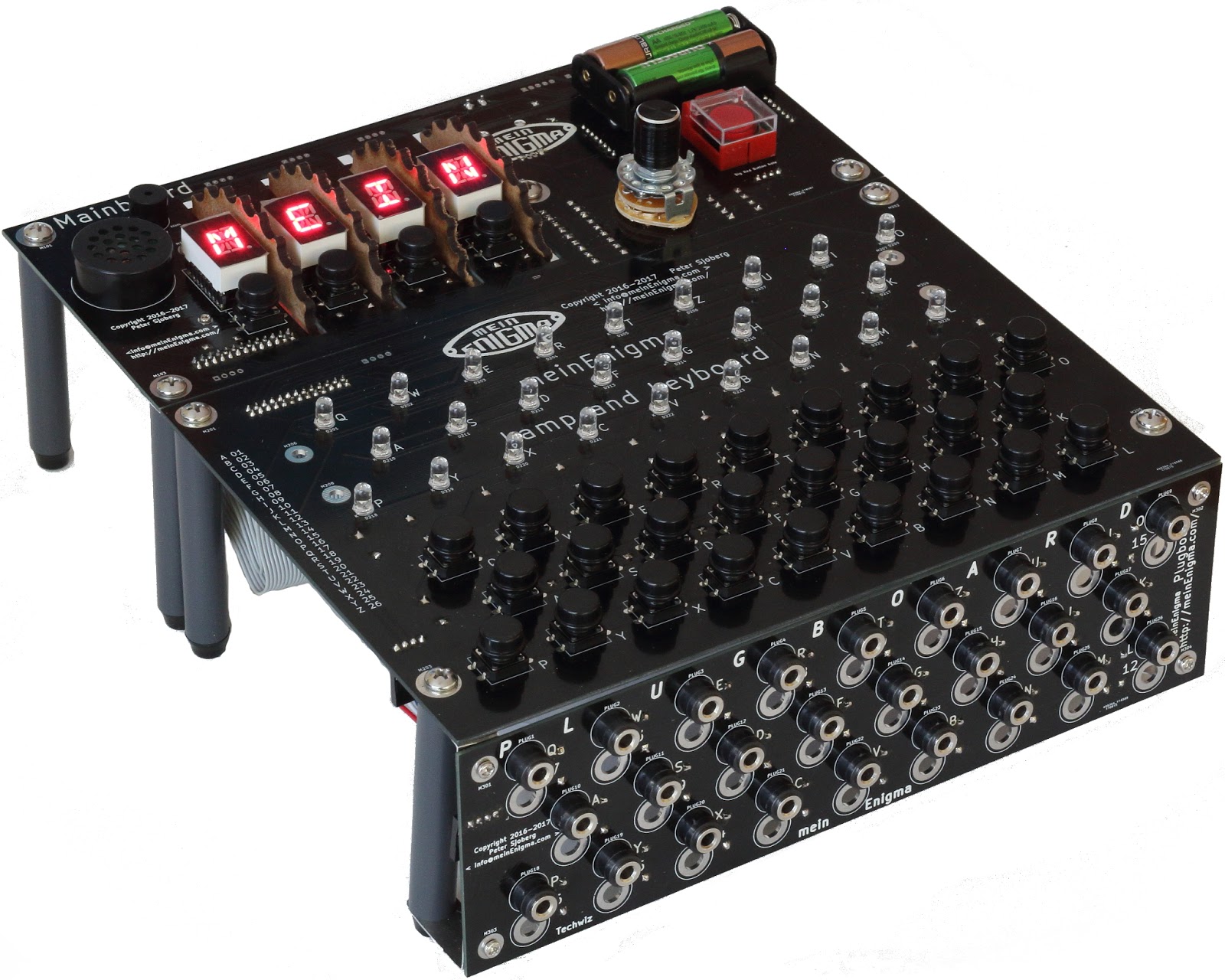
One last update, everything is now "live" on https://meinenigma.com
Kits and even completely assembled enigmas are now available in the store.


No comments:
Post a Comment